This product is manufactured by
HANNZ MOTROL
Manufacturer information
HANNZ MOTROL
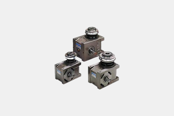
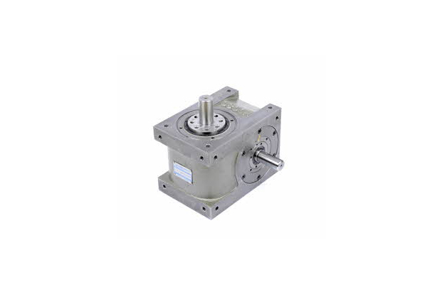
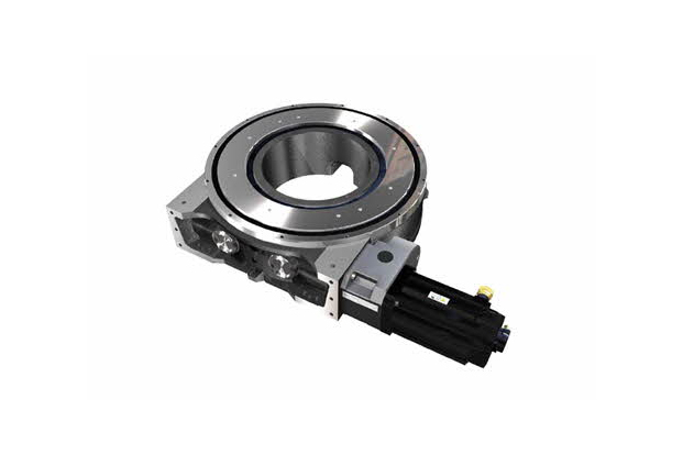
Index drive, CAM, Roller gear type reducer
Inquiry
How to order
Problem with product info?
Update request
Manufacturer
HANNZ MOTROL
Product Type
Machine
Brand
-
SKU
131361
Product Name
INDXIA (HA Series)
Model Name
-
Size
-
Weight
-
Product Details
More products
Gear HeadPGM40
INDXIA (HP Series)
INDXIA (HD Series)
INDXIA (PICK&PLACE)
DynaDrive
TorqueShieldT07B, T09B, T11B, T15B, T19B, T23B
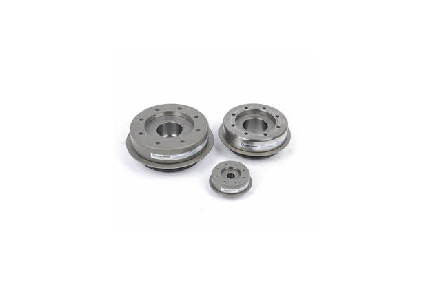
TorqueShieldT06C, T07C, T08C, T11C, T14C
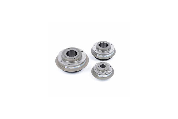
TorqueShieldT06F, T07F, T08F, T11F, T14F, T18F
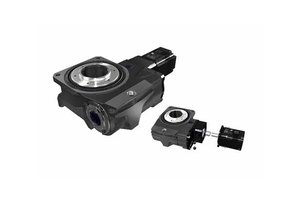
DynaStationGTB40, GTB63, GTB80, GTB100
DynaStationDSR120, DSR160, DSR220, DSR300, DSR400, DSR500
1/3