Do you need to buy machine or parts?
Please email us: help@komachine.com


This product is manufactured by
LS ELECTRIC
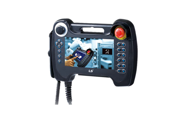
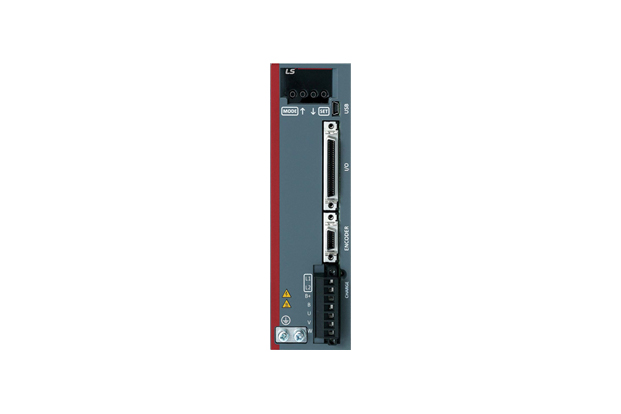
XGT Panel (iXP2H Series (Handheld))
Model Name
iXP2H-0702D Series
Manufacturer information
LS ELECTRIC
Smart Power Solution, Low Voltage, Smart Automation Solution, PLC, Smart Railway Solution, Signaling System and more
Inquiry
How to order
Problem with product info?
Update request
Manufacturer
LS ELECTRIC
Product Type
Machine
Brand
-
SKU
133100
Product Name
XGT Panel (iXP2H Series (Handheld))
Model Name
iXP2H-0702D Series, iXP2H-0704D Series
Size
-
Weight
-
Product Details
More products
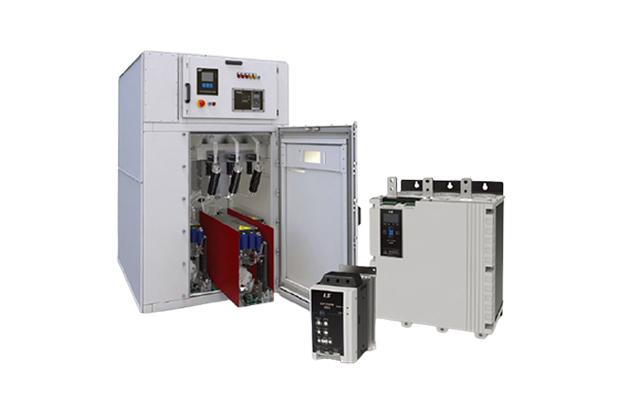
Soft StarterSSCe, SSCi, SSM□, SSH
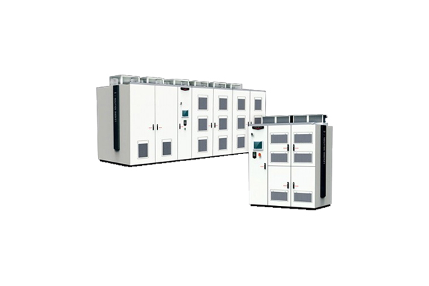
Medium Voltage VFDLSMV-M1000, LSMV-M1000A
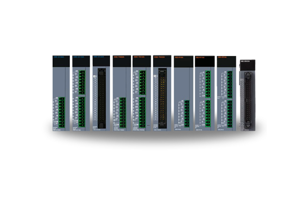
XGB Digital Input/Output ModuleXBE-DC08A, XBE-DC16A, XBE-DC32A, XBE-TN08A, XBE-TP08A, XBE-TN16A, XBE-TP16A, XBE-TN32A, XBE-TP32A, XBF-AD04C, XBE-RY08A, XBE-RY16A, XBF-DV04C, XBF-DC04C, XBE-DR16A, XBE-DN32A, XBE-DN32A
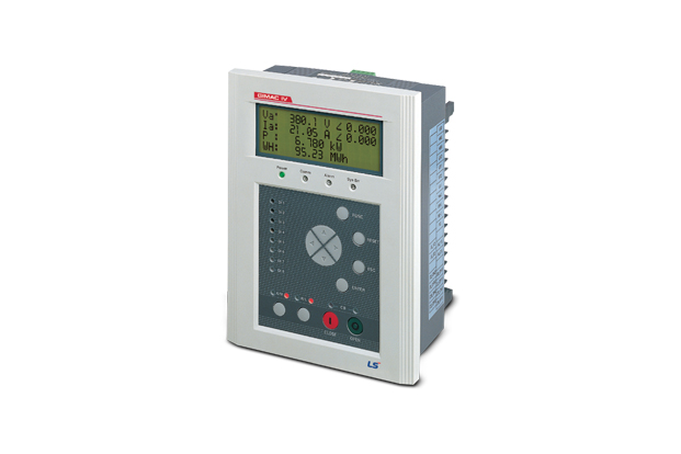
MeasurementGIMAC-IV, GIMAC-415
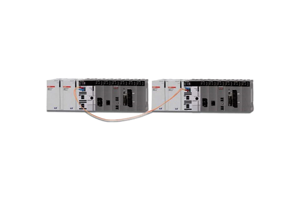
PLC XGR-CPU (XGT Series)
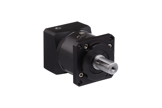
Precision Planetary Gearbox (MSS Series)
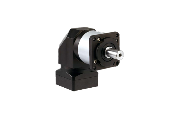
Precision Planetary Gearbox (SAS Series)
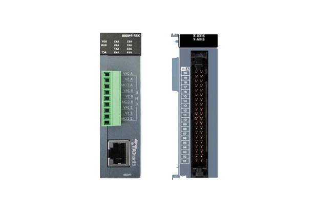
XGB Motion & Positioning module (Motion Controller)
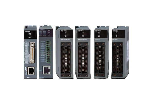
XGT Motion & Positioning Module (Motion Controller)
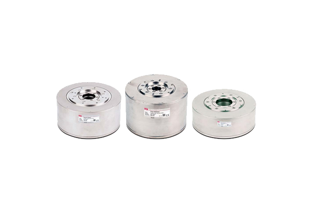
DD Motor (Servo Motor)
Servo DriveL7C
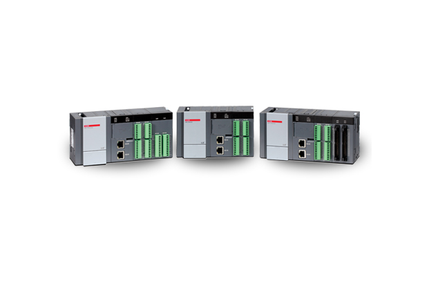
PLC (XGB Series) XBC/XEC U-Type
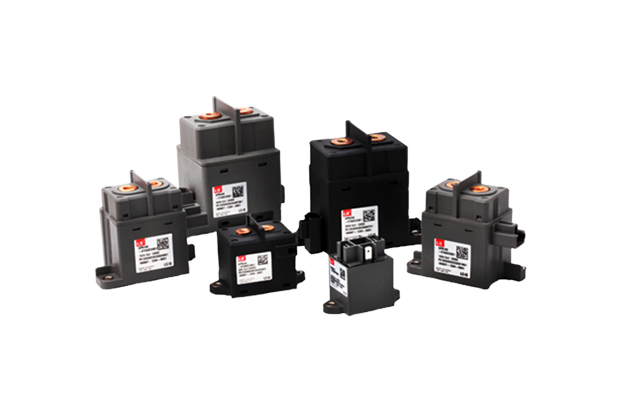
EV Relay
IEC Compact Susol DC Switch- Disconnector
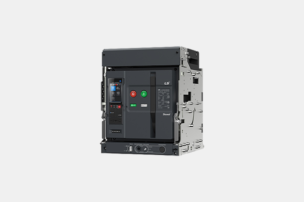
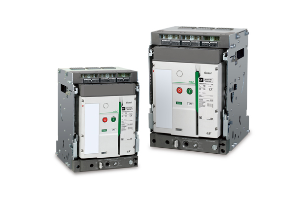
DC ACB & Switch-Disconnector
Susol DC MCCB & Switch-Disconnector
1/4