Smart Power Solution, Low Voltage, Smart Automation Solution, PLC, Smart Railway Solution, Signaling System and more
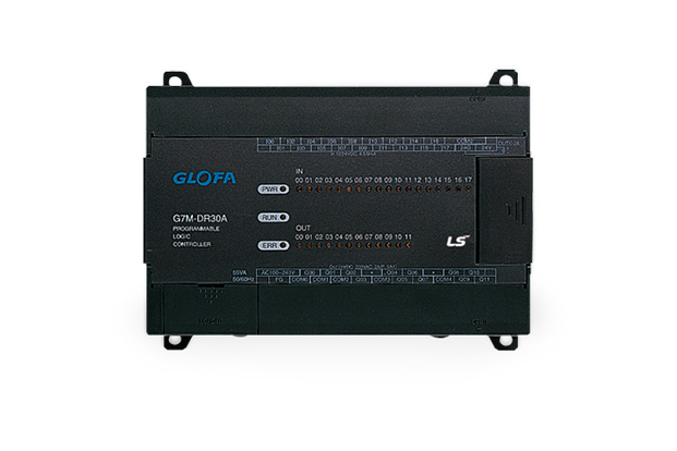
GM7 & GM7U
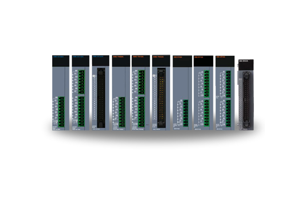
CPU, digital I/O and power are embedded in block-type PLCs, which is easy to install in the area you want for system configuration. In case of module-type PLCs, system configuration is easily achieved by a variety of modules (CPUs, I/O, special modules, network modules).
Features
GM7
ㆍHigh function and high performance with dedicated MPU chip
- IEC 61131-3
ㆍGLOFA-GM Network
- Fnet, Rnet as master module
- DeviceNet, Profibus-DP as slave module
ㆍVarious built-in functions
- High speed counter 1 point (1-phase 16kHz, 2-phase 8kHz
- Pulse output 1 point (2kHz only available in Tr-output module)
- PID loop with autotuning
- Pulse catch 8 points (pulse catch: Min. 0.2ms)
- Input filter (Noise reduction)
- interrupt point: 8 points (Task program execution by external interrupt input)
- RS-232C interface 1 channel (Built-in Cnet):dedicated, User-defined, Modbus protocol
Specification
| Item | Specifications | Remark | ||
|---|---|---|---|---|
| Operation method | Cyclic execution of stored program, Time-driven operation, Internal task operation | |||
| I/O control method | Scan synchronized batch processing method (Refresh method) | Immediate input/output is | ||
| available by ‘Direct I/O’ function | ||||
| Program language | IL (Instruction list) / LD (ladder diagram) / SFC (Sequential function chart) | |||
| Number of Instructions | Operator | LD: 13, IL: 20 | ||
| Standard function | 194 | |||
| Standard function block | 12 | |||
| Special function block | Each special module has its own special function block | |||
| Processing speed | Operator | 0.5㎲ / instruction | ||
| Standard function/function block | 0.5㎲ / step | |||
| Programming memory capacity | 68K | Built-in flash memory (128K) | ||
| I/O points | From 10 to 80 points (according to modules) | |||
| Data Memory | Direct variable area (DVA) | 2~8K | Setting in GMWIN | |
| Symbolic variable area (SVA) | 32K - Direct variable area | |||
| Timer | No limitation. Time range: 0.001~4294967.295 sec (1193 hours) | 20 bytes per 1 timer in SVA | ||
| Counter | No limitation. Count range: -32768~32767 | 8 bytes per 1 counter in SVA | ||
| Operation mode | RUN, STOP, PAUSE, DEBUG | |||
| Data retention at power failure | Set to 'Retain' at data declaration | |||
| Number of program blocks | 100 | |||
| Program type | Task | Scan | 100 - (Number of program blocks in task) | |
| Time-driven | 8 | 8 in total | ||
| Externa | 8 | |||
| Internal | 8 | |||
| Initialization | 1 (_INIT) | |||
| Self-diagnostic function | Watchdog timer, Memory error, I/O error, etc | |||
| Restart mode | Cold, Warm | |||
| Built-in function | PID control | Control by function block, Autotuning, Forward/Reverse operation, Manual output, Operation scan time setting | ||
| Cnet interface | Dedicated, Modbus, User-defined protocol | |||
| HSC | Counting speed | 1-phase 16kHz, 2-phase 8kHz | ||
| Counting method | 1-phase up/down counter (up/down: selection by program) 1-phase up/down counter (up/down: selection by B-phase) 2-phase up/down counter (up/down: Automatic selection by phase difference) |
|||
| Multiplication | 1, 2 or 4 | |||
| Task program running | Task program running when the current value of HSC reaches the setting value | |||
| Pulse catch | Min. pulse width: 2ms, Maximum 8 points available to use | |||
| Pulse output | 2kHz, 1Ch | |||
| External interrupt Input | 8 points | |||
| Input filter function | 0~15ms (Setting by 1ms) | |||
* 1) Built-in RS-232C signal: 4 (Rx), 7 (Tx), 5 (SG)
* G7M-DR10A, G7M-DR10A (/DC), G7M-DT10A: RS-232C and RS-485 port are embedded.
(Simultaneous use is not allowed) and a communication option module is not available.