지금 보고 계신 제품의 제조사에요
암페놀
제품 상세 정보
이 기업의 다른 제품
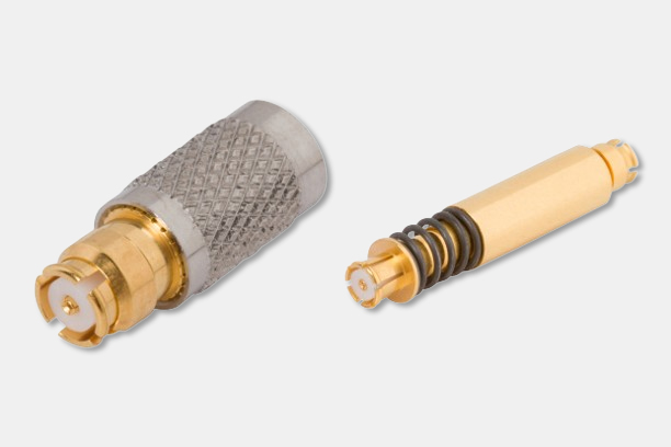
Amphenol NEXUS Plug and Jack Telephone Connectors
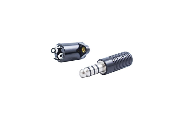
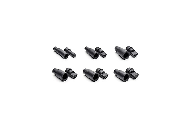
Amphenol NEXUS M55116 MIL-Spec Audio Connectors
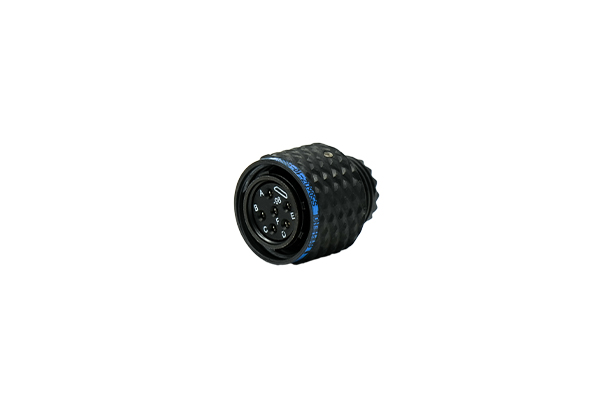
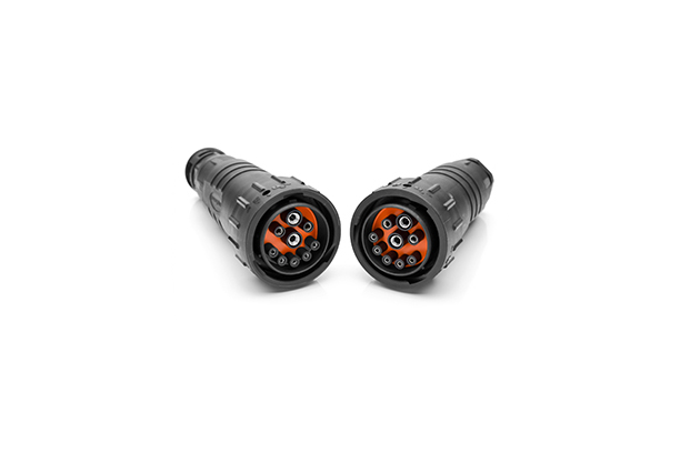
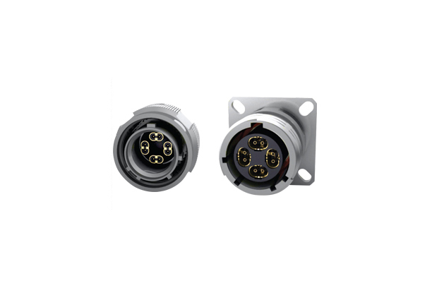
Stingray 7 Series
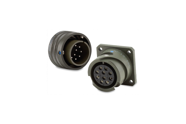
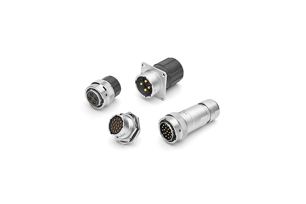
Amphenol Series Five Connectors
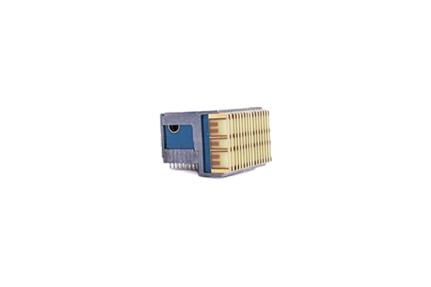
Amphenol Micro-D M83513 Connectors
Amphenol R-VPX Evolution Series
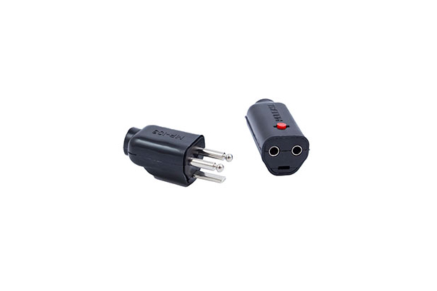
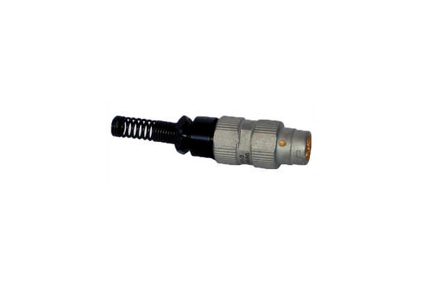
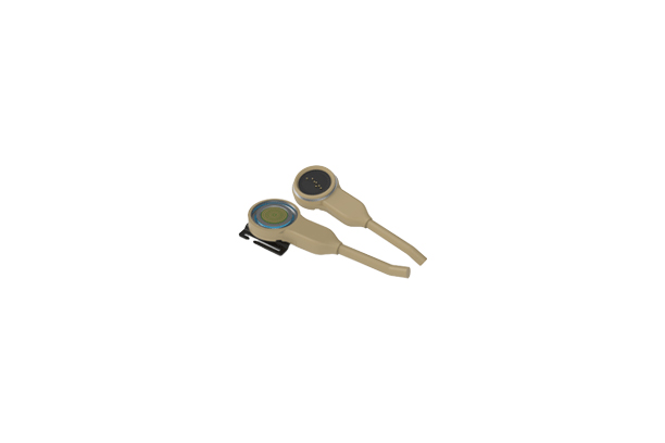
Amphenol NEXUS Plug and Jack Microphone Connectors
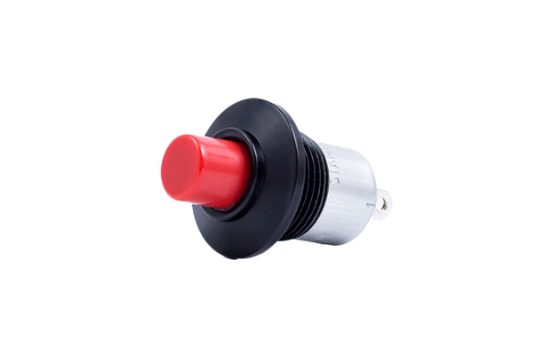
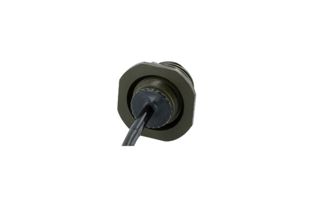
Amphenol NEXUS Waterproof Push-Button Switches
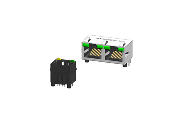
Amphenol Communication Solutions (ACS) RJHSE Modular Jack Connectors
Amphenol Tuchel 44 Series Connectors
Amphenol Sine Systems DuraMate™ AHDP Isobus 91 Series
Amphenol ecomate® RM Connectors
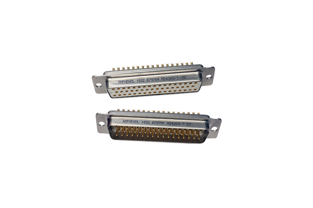
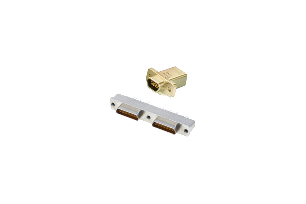
Amphenol Pcd Rack & Panel Type D-Sub Connectors
Amphenol USBFTV (USB-A) Series Connectors
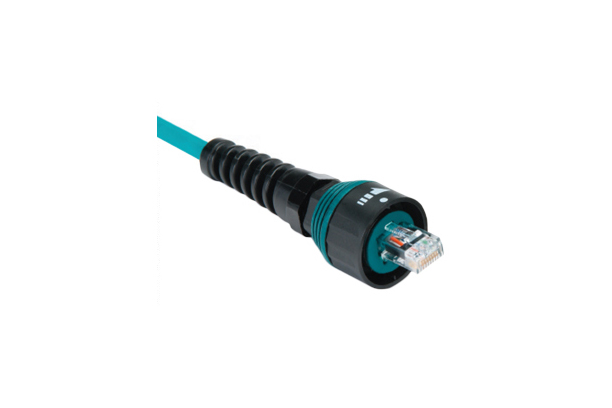
Amphenol Ruggedized Ethernet Connectors (Pulse-Net)
Amphenol OCS High-Speed Connectors (Oval Contact System)
1/4