Do you need to buy machine or parts?
Please email us: help@komachine.com


This product is manufactured by
HITACHI INDUSTRIAL EQUIPMENT SYSTEMS
Manufacturer information
HITACHI INDUSTRIAL EQUIPMENT SYSTEMS
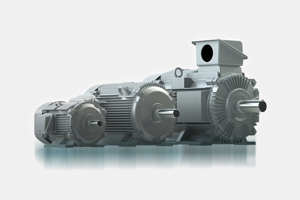
Industrial Electric Motor, Variable Freqency Drives, AC Servo, Water Supply Pump, High-pressure Blowers and more
Inquiry
How to order
Problem with product info?
Update request
Manufacturer
HITACHI INDUSTRIAL EQUIPMENT SYSTEMS
Product Type
Machine
Brand
-
SKU
140241
Product Name
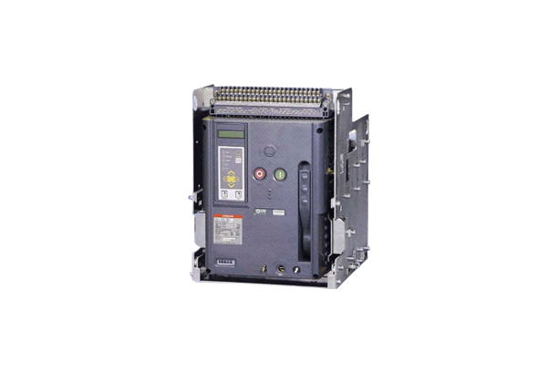
Air Circuit Breakers
Model Name
-
Size
-
Weight
-
Product Details
More products
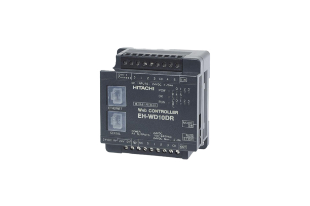
Web ControllerEH-WD10DR, WA23DR
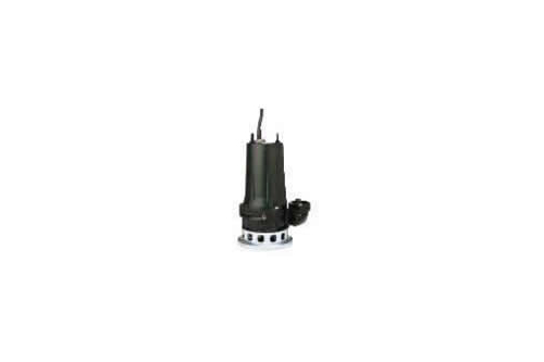
Submersible Pumps (US Type)
Submersible Pumps (FU Type)
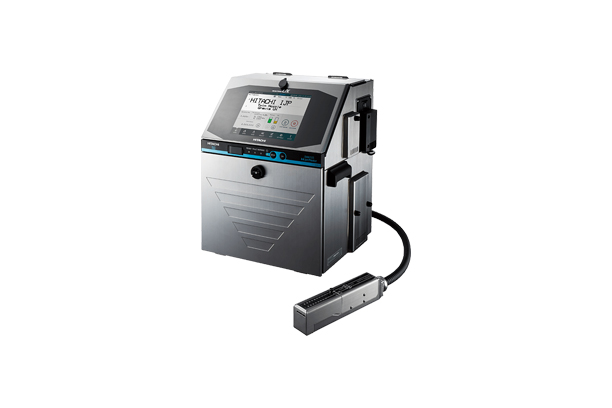
Marking and Coding
Marking and Coding
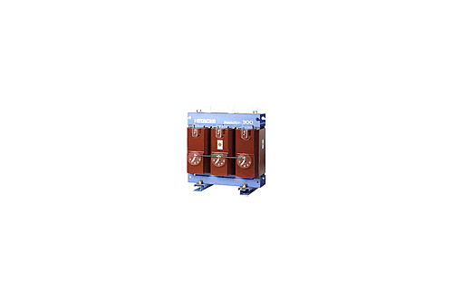
Top-runner Molded Transformers

Molded Transformers (Super Energy Saving Disaster Prevention Compact Type)MC Series
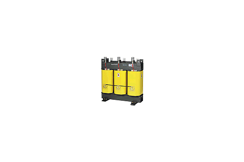
Molded Transformers (Super Energy Saving Disaster Prevention Type)MS Series

Oil-immersed Transformers (Super Energy Saving Small Type)C Series
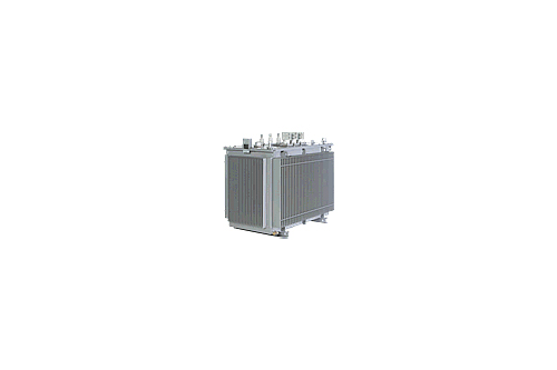
Oil-immersed Transformers (Super Energy Saving Standard Type)S Series

Oil-immersed Transformers (Top-runner Energy Saving Type)SP Series
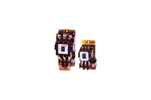
Magnetic Starters & Contactors
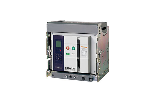
Air Circuit Breakers (AKH, AKS, AKN Series)
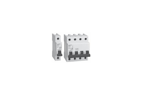
Miniature Circuit Breakers
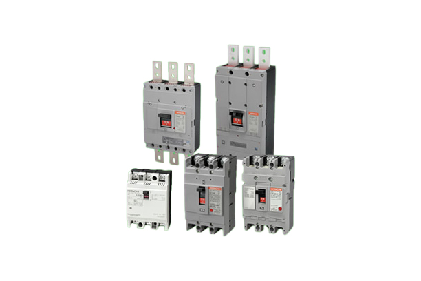
Molded Case Circuit Breakers
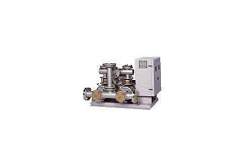
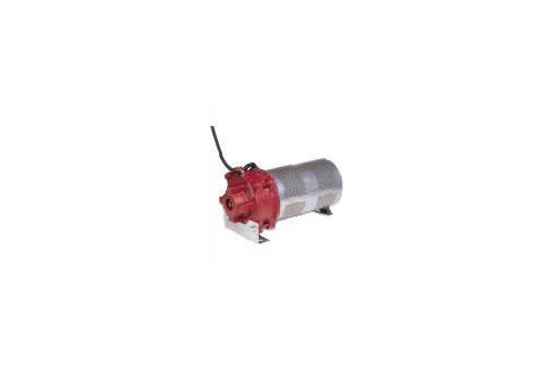
Direct Water Ace
1/4