This product is manufactured by
AMPHENOL
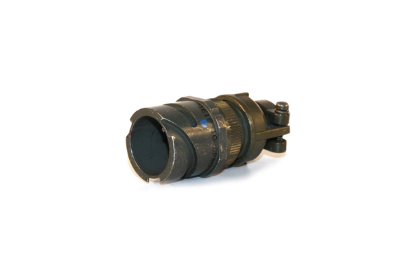
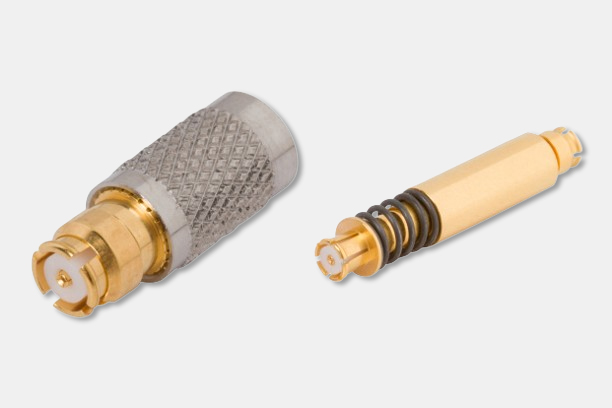
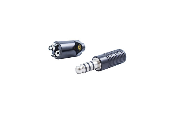
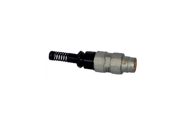
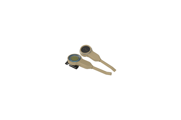
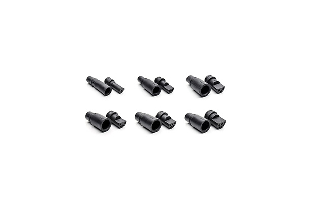
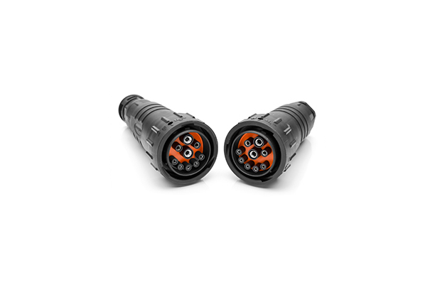
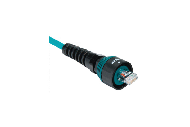
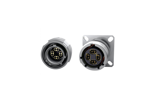
Amphenol ACA-B Series Connectors
Model Name
-
Manufacturer information
AMPHENOL
Interconnect Product Manufacturer, Electrical, Electronic, Fiber Optic Connectors, Coaxial Cable and more
Inquiry
How to order
Problem with product info?
Update request
Manufacturer
AMPHENOL
Product Type
Machine
Brand
-
SKU
141496
Product Name
Amphenol ACA-B Series Connectors
Model Name
-
Size
-
Weight
-
Product Details
More products
Amphenol NEXUS Plug and Jack Telephone Connectors
Amphenol NEXUS M55116 MIL-Spec Audio Connectors
Stingray 7 Series
Amphenol Series Five Connectors
Amphenol Micro-D M83513 Connectors
Amphenol R-VPX Evolution Series
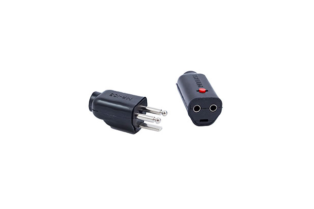
Amphenol NEXUS Plug and Jack Microphone Connectors
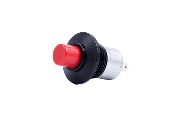
Amphenol NEXUS Waterproof Push-Button Switches
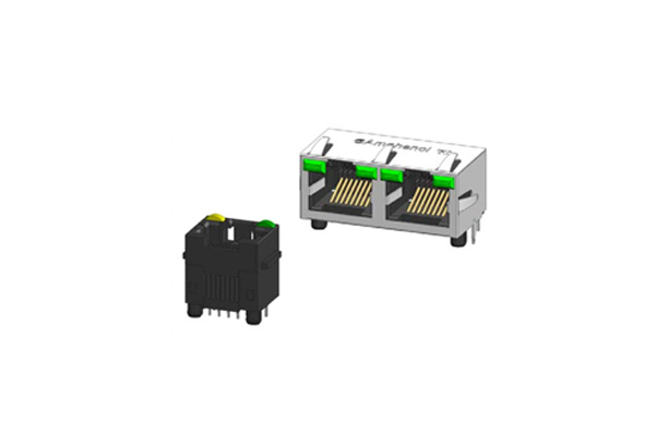
Amphenol Communication Solutions (ACS) RJHSE Modular Jack Connectors
Amphenol Tuchel 44 Series Connectors
Amphenol Sine Systems DuraMate™ AHDP Isobus 91 Series
Amphenol ecomate® RM Connectors
Amphenol Pcd Rack & Panel Type D-Sub Connectors
Amphenol USBFTV (USB-A) Series Connectors
Amphenol Ruggedized Ethernet Connectors (Pulse-Net)
Amphenol OCS High-Speed Connectors (Oval Contact System)
1/4