


This product is manufactured by
SHILLA FIRE
Manufacturer information
SHILLA FIRE
Fire fighting products, Nozzle, Monitor, Valve, Connector, Fire hydrant and more
Inquiry
How to order
Problem with product info?
Update request
Manufacturer
SHILLA FIRE
Product Type
Machine
Brand
-
SKU
134839
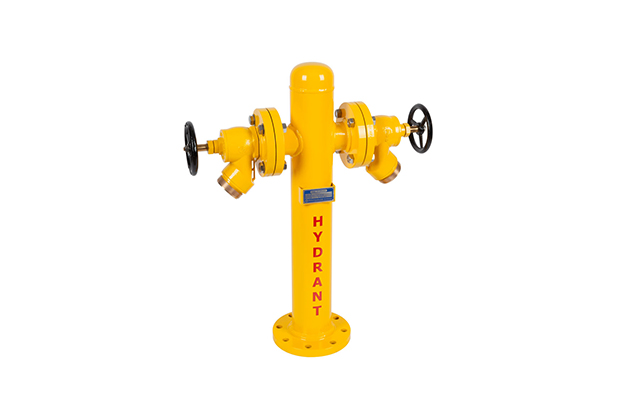
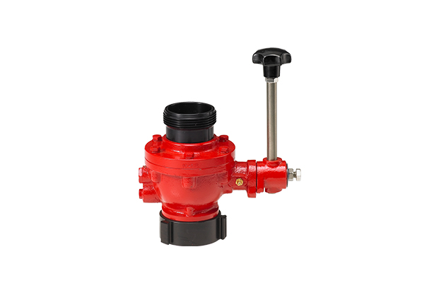
Product Name
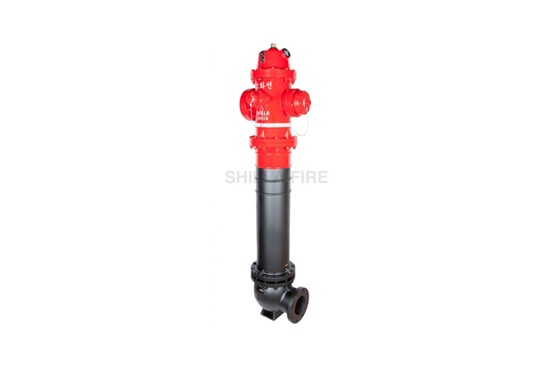
Dry Barrel Hydrant
Model Name
SLH-150FG-A, SLH-150FG-B, SLH-150FG-C, SLH-150FG-D, SLH-150FG-E, SLH-150FG-F, SLH-150TG-A, SLH-150TG-B, SLH-150TG-C, SLH-150TG-D, SLH-150TG-E, SLH-150TG-F, SLH-150F-A, SLH-150F-B, SLH-150F-C, SLH-150F-D, SLH-150F-E, SLH-150F-F, SLH-150T, SLH-150D-B, SLH-150D-C, SLH-150D-D-A, SLH-150T-B, SLH-150T-C, SLH-150T-D, SLH-150T-E, SLH-150T-F
Size
-
Weight
-
Product Details
More products
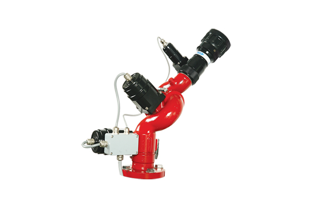
Remote Controlled MonitorSL-26NES, SL-26NE, SL-26HE
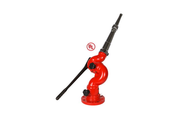
Manual Operation Type (Lever Operation Type)SL-23N-2K, SL-23NB-2K, SL-23N-2, SL-23NB-2, SL-23N-3, SL-23NB-3, SL-23N-4, SL-23NB-4, SL-23N-2, SL-23NB-2, SL-23N-3, SL-23NB-3, SL-23N-4, SL-23NB-4, SL-23A-2K, SL-23A-2, SL-23AB-2, SL-23A-3, SL-23AB-3, SL-23A-4, SL-23AB-4, SL-23G-2K, SL-23G-2, SL-23GB-2, SL-23G-3, SL-23GB-3, SL-23G-4, SL-23GB-4, SL-20S, SL-25S-A, SL-25S-P, SL-25S-F, SL-23WJ-2, SL-23WJ-3, SL-23WJ-4, SL-23WJ-6, SL-23WJ-T
Tester & OthersSL-PT-111, SL-PG-112, SL-57, SL-57A, SL-SP-119
Hose Support ToolSL-75V, SL-75H, SL-61, SL-61A, SL-61R, SL-79, SL-62BR, SL-60H, SL-60HA, SL-120J, SL-120JA
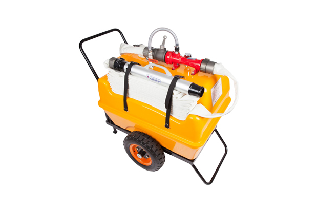
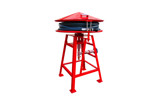
Unit & TrailerSL-2100, SL-2100B, SL-2100F, SL-31-3FT, SL-31-3FTA
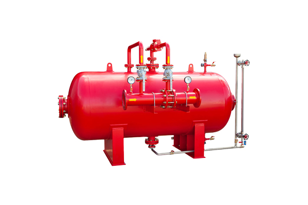
TankSL-HT-100, SL-HT-200, SL-HT-300, SL-HT-400, SL-HT-500, SL-HT-600, SL-HT-700, SL-HT-800, SL-HT-900, SL-HT-1000, SL-HT-1100, S L-HT-1200, SL-HT-3700, SL-VT-100, SL-VT-200, SL-VT-300, SL-VT-400, SL-VT-500, SL-VT-600, SL-VT-700, SL-VT-800, SL-VT-1000
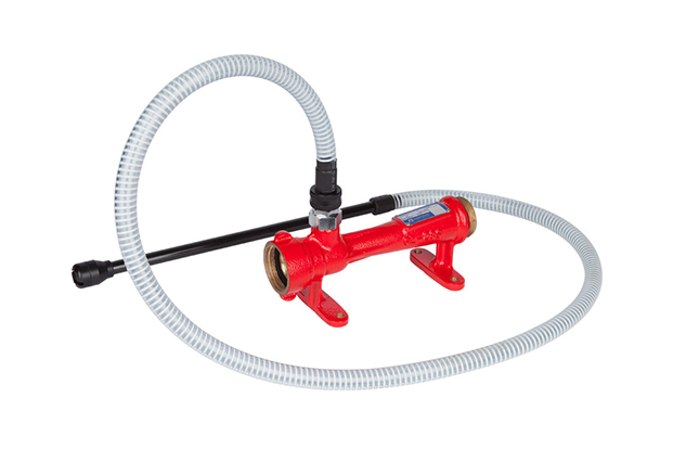
ProportionerSL-28S, SL-28B, SL-29, SL-28C, SLP-6-9, SLP-10-25, SLP-30-40, SLP-45-55, SL-30C-1, SL-30C-2, SLP-65FP, SLP-80FP, SLP-100FP, SLP-150FP, SLP-200FP, SL-DP-80, SL-DP-100, SL-FD-1000, SL-FD-1000B, SL-FD-1600, SL-FD-1600B, SL-FD-2500, SL-FD-2500B, SL-FD-4000, SL-FD-4000B, SL-FD-6000, SL-FD-6000B, SL-FD-8000, SL-FD-8000B, SL-FD-10000, SL-FD-10000B
Wet Barrel HydrantSLS-100, SLS-150P, SLS-150PM
Thread ConnectorSL-49-A, SL-49-A-A, SL-49B-A, SL-49F-A, SL-49K-A, SL-49H-A, SL-49L-A, SL-49C-A, SL-49D-A, SL-49G-A, SL-49E-A, SL-49B-A, SL-49I-A, SL-49J-A, SL-51-A, SL-51A-A, SL-51C-A, SL-51D-A, SL-51F-A, SL-51E-A, SL-51G-A, SL-51B-A, SL-51J-A, SL-51S-A, SL-51K-A, SL-51H-A, SL-50, SL-50ES, SL-50EA, SL-50M-A, SL-50BA, SL-50C-AA, SL-50D-AA, SL-50D-A, SL-50H-A, SL-50I-A, SL-54-A, SL-50FA, SL-54A-A
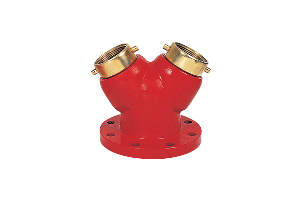
“Y” Type ConnectorSL-33, SL-36S, SL-36, SL-36A, SL-36AF, SL-33M, SL-35S, SL-35
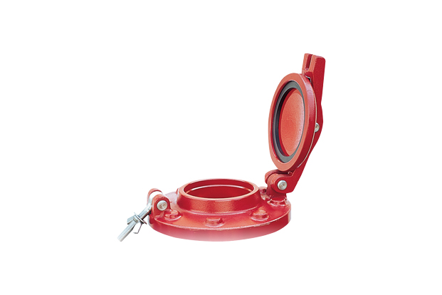
Hose ValveSLB-R40, SLB-40P, SLB-65P, SLB-40S, SLB-40, SLB-65
Hydrant ValveSL-41F-A, SL-41Q-A, SL-41FH-A, SL-41FQ-A, SL-48A-A, SL-48MC-A, SL-41F, SL-41Q, SL-41FH, SL-41FQ, SL-48A, SL-48MC, SL-40G, SL-40GF, SL-40GF-2, SL-40GQ, SL-40F, SL-40Q, SL-40FH, SL-40FQ, SL-40FM, SL-40GN, SL-40F, SL-40Q, SL-42PRF, SL-42PRF-GS, SL-42PRF-M, SL-42PRF-BSQ, SL-39, SL-39A, SL-39P, SL-39PA
Foam NozzleSL-17S, SL-17, SL-17PS, SL-19MS, SL-19MP, SL-19MB, SL-19MS-B, SL-19MP-B, SL-17SQ, SL-17Q, SL-17PSQ, SL-19MSQ, SL-19MPQ, SL-19MBQ, SL-19MSQ-B, SL-19MQ-B, SL-19M, SL-19GM, SL-19GMA, SL-19GMA-3, SL-19GML-2, SL-19GML-3, SL-15FNA-500, SL-15FNA-750, SL-15FNA-1000, SL-15FN-500, SL-15FN-750
Monitor NozzleSL-8SS, SL-8SF-B, SL-8SFG-B, SL-8SF, SL-16JN-500, SL-16JN-750, SL-16JN-1000, SL-16CJ, SL-16J, SL-16NR, SL-16SN, SL-16NW, SL-16JNW-2, SL-16JNW-3, SL-16MSW-3, SL-16SNEA, SL-16NEA, SL-16JNEA, SL-16MSE-3, SL-8SFE, SL-16NE, SL-16JNE
Hose NozzleSL-9, SL-9A, SL-10A, SL-11A, SL-10, SL-11, SL-D200, SL-D200A, SL-10MSL-11M, SL-9N, SL-10S, SL-11S, SL-10NW, SL-11NW, SL-10NWQ, SL-11NWQ, SL-11DSL-11Q
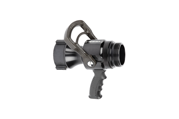
Pistol NozzleSL-13AN, SL-13BN, SL-12, BP-25, SL-12DBS, SL-12BPS, SL-13SP, SL-13BP, SL-13SPQ, SL-13BPQ, SL-13DBS, SL-13BPS, SL-13DBSQ, SL-13BPSQ, SL-13DB-B, SL-13SP-B, SL-13BP-B, SL-14S, SL-14SQ, SL-15B, SL-15BQ
1/4
