Search

S&S

S&S

S&S

S&S

HomeManufacturersS&S
1/1
S&S

S&S

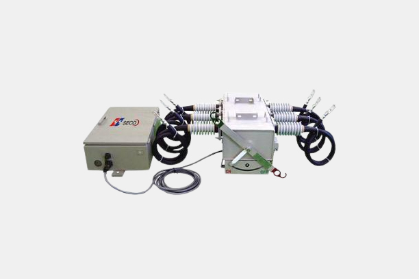
Control Unit for Motorized SF6 Load Break Switch

Model

Series

Distribution Switches - Load Break Switches


Transaction Process

Please contact the manufacturer/supplier.

Payment

Contact the manufacturer/supplier.

Delivery

Contact the manufacturer/supplier.

Shipment

Contact the manufacturer/supplier.

Origin

Contact the manufacturer/supplier.


Description

Overview

  Control unit was designed to work locally and remotely with motorized type SGS Load Break Switch for overhead lines. It can communicate with SCADA or DAS via RTU and MODEM.

Product Highlights
   - Control cubicle is fabricated from stainless steel sheet of not less than 2 mm in thickness  and suitable for mounting on a pole through a steel channel fixed to the back of the cabinet  for mounting purpose. It has the characteristics for good thermal insulation, ventilation and  water penetration, and is installed with grounding terminal connector and padlock etc.
   - Electrical surge protection and impedance-matching control circuit board is constructed and tested to meet the latest applicable standards of IEC 60255 and ANSI/IEEE C37.90.1.
   - Lead acid battery provides DC power to the local control circuit board in case of AC power source failure. The battery has sufficient capacity to sustain more than 24 hour operation while AC power supply’s failure, with a minimum lifetime of 3 years.
     The battery is automatically disconnected from the control circuit when the battery voltage falls below a preset value in order to prevent deep battery discharging.
   - Auxiliary power cable and control cable with outdoor-rate connectors at each end to connect the mating receptacles on the load break switch and on the bottom of the control cabinet. The control cables are shielded from electromagnetic interface(EMI) and radio frequency interface.

Power Supply
   - AC power supply from power source inputs 220VAC to the control unit, and DC power 24VDC is parallel connected with battery and the other part of the control circuit.
   - Battery charger has trickle charging mode and protecting function of over charging.
     Battery : lead acid battery 18Ah and 24VDC input toward control circuit.

Local Control Circuit
   - 3 CT signal(1000 : 1, but other ratio selectable) and 6 voltage signal output(4 VAC output but  other value available) from the load break switch.
   - Battery testing to check the battery voltage on load condition & battery charger.
   - Local/Remote control selection switch.
   - Local close/open button.
   - Separate Open(green) and Close(red) status LED.
   - Low gas pressure status LED.

RTU for remote control (option)
   The RTU can be supplied to communicate with center control, to measure the electrical quantity, and to get the fault information.
   It is using the DSP for calculation and micro-processor for other tasks. It can measure the V, I, VA, W, VAR and power factor, detect the fault current and memory the wave form for further analysis.

   - Hardware
   □ Total 14 status monitoring points
       Open / Close / Earth status
       Lock / Unlock status
       Local / Remote status
       Gas pressure status
   □ Total 9 measuring input points
       3 Current of each phase
       6 Voltage of each phase
   □ Total 8 control output points
       Open / Close control signal
       Lock / Unlock control signal
       Battery test control signal

   - Measurement
   □ Instantaneous metering
       Currents          I / a,b,c,n input current
       Voltages         V / a,b,c wye-connected voltage inputs
       Power            MW / a,b,c mega-watts(wye-connected voltage inputs only)
                           MVAR / a,b,c mega-vars(wye-connected voltage inputs only)
       Power factor   PF / a,b,c power factor : leading or lagging
   □ Demand metering
       Currents          I / a,b,c,n input currents
       Power            MW / a,b,c mega-watts(wye-connected voltage inputs only)
                           MVAR / a,b,c mega-vars(wye-connected voltage inputs only)
   □ Max. / Min. metering
       Currents         I / a,b,c,n input currents
       Power          MW / 3p 3 phase mega-watts
                         MVAR / 3p 3 phase mega-vars

   - Events
   Many kinds of events with time tags are useful for analysis of the switch, RTU, communication and power line.
   □ Power - on / off
   □ Ext. Power - on /off
   □ Self testing result
   □ Change the settings
   □ Switch - close / open (remote/local communication port)
   □ Lock / Unlock
   □ Low gas
   □ Low battery
   □ Line voltage - on / off, source side / load side
   □ Fault - pick up / drop out
   □ Phase discord
   □ One or two loss of line voltage

   - Fault Indicator
   The fault information is used for identifying the faulted section. It has the special logics to distinguish the temporary fault and permanent fault.
   □ Inrush restraint feature ; If the current changes from normal current to 0 current, then it blocks the pick-up within preprogrammed time.
   □ Pre-detecting time(software programmable) ; If the over current condition lasts more than this time, it is validated as the start of a potential fault.
   □ In progress ; It memories the current, voltage, wave form until the over current condition finishes, and it takes the maximum rms fault current.
   □ Final ; If the over current condition is finished and the current goes to 0 (back up protection device clears the fault) or goes to normal current (forward protection device clears the fault), it waits the maximum reclosing interval of back up device, and when the programmed time elapse it finally decides whether the over current was temporary or permanent fault.
      Every effective over current condition is recorded as the events and the final temporary or permanent fault information is recorded as fault indicator information.
      It consists of start time, fault current level, end time, number of over load conditions and temporary or permanent fault information. The fault indicator can check the forward fault or reverse fault to give the correct fault information.

   - Communication Ports
  

PORT 1  MODEM  DNP 3.0 level 2
 Communication rate  9600 bps(programmable)
 Interface  RS-232C
PORT 2  Notebook  
 Communication rate  19200bps (programmable)
 Interface  RS-232C


Download

Outline Drawing

Inquiry

Komachine Inc.
Head Office:
Ace Dongbaek Tower 1-1101, 16-4,
Dongbaekjungang-ro 16beon-gil, Giheung-gu,
Yongin City, Gyeonggido, South Korea 17015
Branch Office:
606, Seoul Stratup Center, 10,
Noryangjin-ro, Dongjak-gu, Seoul, South Korea 06938
CEOCharlie Park
Corporate #535-86-00664

ⓒ2024 Komachine Inc. All rights reserved.