LS일렉트릭(주)
XGT Panel (iXP2H Series (Handheld))
모델명
시리즈
HMI (Smart Automation Solution)
구매 안내
아래는 참고용 정보이므로 세부 조건은 반드시 제조사/판매자에게 문의 바랍니다.
결제 방법
제조사/판매자에게 문의 바랍니다.
납기 정보
제조사/판매자에게 문의 바랍니다.
배송 정보
제조사/판매자에게 문의 바랍니다.
원산지
제조사/판매자에게 문의 바랍니다.
제품 상세 설명
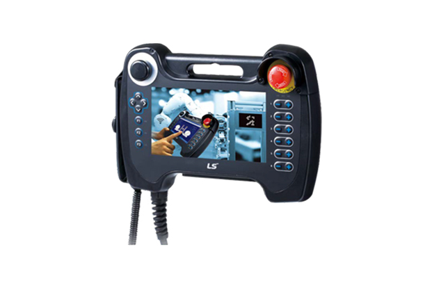
iXP2H Series (Handheld)
New Handyheld HMI iXP2H Series
Features
3-Position Enable Switch

Clear Visibility
ㆍExcellent visibility with high definition and wide screen view
ㆍ1024 X 600 resolution
ㆍ16M color

Project Transfer
ㆍEasy project creation by XP-Builder
ㆍConvenient downloading/uploading of project files via USB port and ethernet (Multi-language supported)

Specifications
| Model | iXP2H-0702D Series | iXP2H-0704D Series | |
|---|---|---|---|
| Display type | TFT color LCD | ||
| Screen size | 7” | ||
| Resolution | 1024 x 600 pixels | ||
| Color indication | 24-bit color (16.7M colors) | ||
| Backlight | LED method, Automatic On/Off support | ||
| Backlight lifetime | 50,000 hours | ||
| Touch panel | Resistive overlay (Pressure type) | ||
| Audio | Magnetic buzzer (12Ø 85 dB) | ||
| Processor | ARM Cortex-A9 800 MHz, single core | ||
| Memory | Flash | 8 GB (Small memory: 128 MB) | |
| Operating RAM | 1 GB | ||
| Backup RAM | 1 MB | ||
| Backup type | Date/time data, logging, alarm, recipe data, non-volatile device | ||
| Battery | CR1220 (3.0V/210 mAh, Around 3 years/25℃) | ||
| Ethernet | 1 x 10Base-T/100Base-TX | ||
| USB host | 1 x USB 2.0 (Below x 1) | ||
| RS-232C | 1 x RS-232C (Terminal block) | - | |
| RS-485 | - | 1 x RS-485 (Terminal block) | |
| Multiple languages | Simultaneous display of 12 languages | ||
| Animation | GIF format support | ||
| Recipe | Supported | ||
| Data logging | Supported | ||
| Script launcher | Supported | ||
| Standard certification | CE, KC | ||
| Protection standard | IP42 (Front) | ||
| Dimensions (mm) | 195×270×72 (Excluding cables) | ||
| Power | DC 24 V ±5% | ||
| Power consumption (W) | 12 | ||
| Weight (Kg) | 1.0 (Excluding cables) | ||
System Configuration and features
Front

① TFT-LCD
1024 x 600 TFT LCD, 16.7M color display
Resistive overlay
② Emergency Stop Switch
Immediately stops the control device or turns off the power as a safety feature
③ Left Keypad
Direction key
F1, F2, F3: User defined
④ Right Keypad
User defined
* Generally used as shortcut key of each axis of robot.
⑤ Extension device
Slot of the USB extension device
• When shipped, it is fastened with a separate cover.
• When used, the cover can be removed witha Phillips head(+) screwdriver for use.
Device Detail

⑥ Reset Switch
Switch for resetting the system
⑦ Debug Port
A debugging port for developers
⑧ USB Host
Connect to USB memory: Backup and send logging, recipe, alarm, and project data.
Connect to user interface: Use the mouse and keyboard.
⑨ USB Device(option)
USB device port(unsupported)
⑩ SD - Card
Software update
SD memory (store data)
Rear

⑪ Enable Switch
Released : Disable
Intermediate : Enable
Fully Pressed : Disable
Junction box

① Ethernet Port
Ethernet : 10Base-T/100Base-TX/1000Base-T
• Connector for Ethernet connection
② Serial terminal block
RS-485/232C communication connector
• 0702D(for RS-232 model): Tx, Rx, GND
• 0704D(for RS-485 model): TRx+, TRx-
③ Switch 2 terminal block
Signal that is controlled from the front side switch of the product.\
• Enable, Emergency(A contact, B contact) switch
④ Switch 1 terminal block
Signal that is controlled from the front side switch of the product.
• Enable, Emergency(A contact, B contact) switch
⑤ N.C
Not used
⑥ Power terminal block
DC 24 V input terminal block