암페놀
Amphenol MB Series Connectors (MIL-DTL-26482 Series II)
모델명
시리즈
Connectors
구매 안내
아래는 참고용 정보이므로 세부 조건은 반드시 제조사/판매자에게 문의 바랍니다.
결제 방법
제조사/판매자에게 문의 바랍니다.
납기 정보
제조사/판매자에게 문의 바랍니다.
배송 정보
제조사/판매자에게 문의 바랍니다.
원산지
제조사/판매자에게 문의 바랍니다.
제품 상세 설명
HIGH-PERFORMANCE MINIATURE CONNECTOR PERFECT FOR AEROSPACE APPLICATIONS
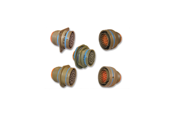
Amphenol’s MB MIL-DTL-26482 series II (Matrix®) miniature cylindrical connectors have a quick-mating, three-point bayonet coupling system. Given their small size and high-quality contact retention and seal, MB series connectors are excellent for high-reliability applications in the harshest conditions, including the aerospace industry. These connectors intermate with all MIL-DTL-26482 series I connectors. Space-rated Class G outgassing is available in 48 hours. For full product details on Amphenol MB series connectors, please see the specifications below.
Get shopping! Mil Spec prefixes include MS3470, MS3471, MS3472, MS3474, MS3476 and MS3475. Amphenol's proprietary prefix is MB.
Features
- High-quality contact system
Amphenol’s MB connector series uses industry-standard M39029 crimp-style contacts and a field-proven contact retention clip that locks the contact into place while allowing easy insertion and removal with simple, low-cost plastic tools. - Wide range of cable accessories, including military-standard
Unlike MIL-DTL-26482 series I style connectors, MIL-DTL-26482 Series II style are supplied without rear accessories but with military-standard rear threads. This permits a choice from one of the broadest array of endbells, including M85049-standard endbells, and from low-cost, simple cable tie versions to fully environmentally-sealed EMI-shielded endbells. - Broad operating temperatures
MBs use high-quality silicone for the peripheral, interfacial and wire seals. This, along with the stable hard dielectric insert material that houses the contact retention clip, provide operating temperatures from -67°F to +392°F (-55°C to +200°C). - Rear contact insertion and release system
Used properly, the insertion and extraction tools never touch, come in contact with or damage the interfacial seals, eliminating a common problem with front-release contact systems. - Cork-in-a-bottle interfacial seal system
Socket inserts have hard, dielectric, funnel-shaped contact lead-ins that not only assist in aligning the contacts when mating, but provide compression of the raised individual contact seals on the high-quality silicone interfacial seals of the pin insert.
Materials & Finishes
Electrical Data
Working & Test Voltage

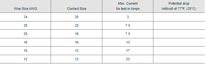
Current Rating
Class L and 347°F (175°C) Class W
Mechanical
Operating TemperatureElectroless nickel and olive drab chromate over cadmium over nickel
-67°F up to +392°F (-55°C up to +200°C)
Wire Sealing Range

Insulation Strip Length

All dimensions in inches (millimeters in parentheses)

Excerpt from MIL-DTL-26482H
3.7.4 JAN and J marking. The United States Government has adopted and is exercising legitimate control over the certification marks “JAN” and “J”, respectively, to indicate that items so marked or identified are manufactured to, and meet all the requirements of specifications. Accordingly, items acquired to, and meeting all of the criteria specified herein and in applicable specifications shall bear the certification mark “JAN” except that items too small to bear the certification mark “JAN” shall bear the letter “J”. The “JAN” or “J” shall be placed immediately before the PIN except that if such location would place a hardship on the manufacturer in connection with such marking, the “JAN” or “J” may be located on the first line above or below the PIN. Items furnished under contracts or orders which either permit or require deviation from the conditions or requirements specified herein or in applicable specifications shall not bear “JAN” or “J”. In the event an item fails to meet the requirements of this specification and the applicable specification sheets, the manufacturer shall remove completely the military PIN and the “JAN” or the “J” from the sample tested and also from all the items represented by the sample. The “JAN” or “J” certification mark shall not be used on products acquired to contractor drawings or specification. The United States Government has obtained Certificate of Registration Number 504,860 for the certification mark “JAN” and Registration Number 1,586,261 for the certification mark “J”.
PIN = Part Identification Number