M&C ENGINEERING
M&C ENGINEERING
Description
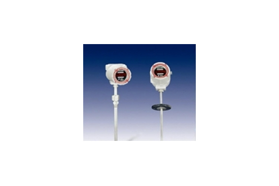
Thermal Insertion Probe Model 62-9/9500
With Integral Microprocessor Electronics
A uniquely designed microprocessor controlled electronics provides integral local control and display in an explosion proof housing. Optional Remote Mounting of the electronics to a distance of 4000ft provides additional versatility depending on the application.
Flow signal linearity and temperature effects, determined at calibration, are corrected by the microprocessor using operating parameter data stored in EEPROM memory.
How it works
It's really very simple.
Our Thermal Mass Flow Meters operate using a constant temperature system that employs two RTD sensors; one for sensing temperature, and one for sensing flow.
The sensor is heated to a precise temperature above that of the fluid passing by. The fluid conducts heat off the sensor in direct proportion to the mass flow rate.
The temperature is used to set the heat on the flow sensor and correct for changes in the fluid temperature.
- Inserts directly into the flow stream; Suited for stacks irregularly shaped lines, square ducts.
- No apertures to become clogged with particles or by heat.
- Stable average output signal; Unaffected by sporadic effects of cross winds.
- Sensors located in the inside leading edge of probe.
- Single probe, rugged design for longer life.
- Can be hot tapped into the system.


Specification
Accuracy: +/- .50% of Full Scale, [or 2.0% of reading whichever is better. Full Scale over the calibrated range. [Process fluid temperature span +/- 50°F]
Repeatability: +/- 0.2 % of Rate
Response Time:
Gases: 1 to 2 sec. Typical
Liquids: Less than 500ms
Pressure Rating:
0 - 1200 psig (Std)
0 - 10000 psig Dependent on meter size
Mass Flow Rates:
Gas: 40 to 50,000 SFPM
Liquid: .02 to 20 FPS
Note: maximum determined by pipe capacity
Flow Range: 100:1 Std. Multiple ranges available
Calibrated Temperature Range:
Gas: -20 F to 350 F (-28°C to 162°C )STD.
[-20°F to 1000°F] (-28°C to 538°C) Optional)
Liquid: -20F to 350F (-28°C to 162°C ) STD.
[ -20°F to 500°F](-28°C to 2691°C) Optional
Wetted Materials: 316SS (STD). Consult the factory for other material requirements
Mounting: Flange, Packing Gland, Triclover, Hot Tap
Calibration Temperature Capability: -20°F to 1000°F(-29°C to 538°C)
MICROPROCESSOR SPECIFICATIONS:
EEPROM Memory: 64K
Displays: 8 digit Flowrate and Totalizer (Optional)
Communicator:
Interface: RS-232 via Ribbon Connector
Baud Rate: 9600
Filter Factor
Flow Full Scale
Flow Rate Decimal Point
Flow Totalizer Decimal Point
Flow Totalizer Flowrate Ratio
Power:
120/240 vat, 50/60 Hz.
24VDC, 1 Amp (Factory Set)
Electrical Connections:3/4” FNPT Power & Signal
Enclosure: Cast Aluminum, Epoxy Painted
Environmental Ratings:
Housing: Explosion Proof, Class 1, Div. 1, Groups, B, C D
Weatherproof: Nema 4
Ambient Temperature: -25 to 60 C (-13 to 140 F)
Storage Temperature: -40 to 70 C ( -40 to 158F )
Mounting:
Integral to the Flow Transducer
Remote to 4000 ft., Wall or Frame mount
Signal Cable for Remote Design: 18 gauge, 2 pair with cable shield. Maximum distance, 4000 ft.
MODEL NUMBERING SYSTEM:
Base Model: = 9500
Electronics Mounting:
I = Integral Mount
R = Remote Mount
F = Fluid
G = Gas
L = Liquid
Probe Size: % to 2” (See Sizing Tables for Gas and Liquid).
Material:
316SS = STD
Other = Consult Factory
Process Connection:
PG = Packing Gland (Std.)
FLG-150 =150# RF Flange (Std.Van stone)
TC = Triclover
FLG-Other = Consult Factory
Other = Consult Factory
Power:
24 = 22-26 VDC, 1 AMP. 4 WIRE
120 = 120VAC, 50/60 HZ (STD.)
240 = 240VAC 50/60 HZ
Output Signals:
(Select One**)
0/5 = 0-5 VDC**
0/10 = 0-10 VDC**
4/20 = 4-20 mADC** into 750 ohms, Isolated std, Self Powered
4/20T = Opt Process Fluid Temp. 4-20mA Self Powered
Other = Consult Factory
Display: (Optional)
ND = No Display
D = Flowrate Display, 8 Digit
8T = Totalizer
D/8T = Flowrate and Total Display, 8 digit
Signal Cable for Remote Design: SC25 = 25 FT Supplied with remote configuration
Dimension

Sizing Guide
