M&C ENGINEERING
M&C ENGINEERING
Description
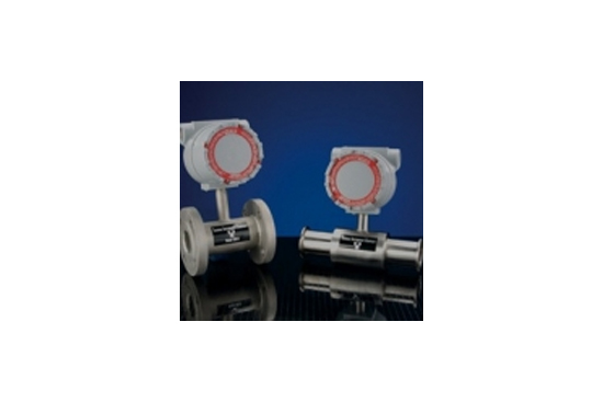
Thermal In-Line Flowmeter Model 600-9/9500
With 일체형 마이크로 전자 공학
A uniquely designed microprocessor controlled electronics provides integral local control and display in an explosion proof housing. Optional Remote Mounting of the electronics to a distance of 4000ft from the flow transducer provides additional versatility.
Flow signal linearity and temperature effects, determined at calibration, are corrected by the microprocessor using operating parameter data stored in EEPROM memory.
How it works
It's really very simple.
Our Thermal Mass Flow Meters operate using a constant temperature system that employs two RTD sensors; one for sensing temperature, and one for sensing flow. The sensor is heated to a precise temperature above that of the fluid passing by.
The Fluid conducts heat off the sensor in direct proportion to the mass flow rate. The temperature is used to set the heat on the flow sensor and correct for changes in the fluid temperature.
- Completely unobstructed flow; Sensor is incorporated into the outer surface protected from adverse conditions and out of the flow path.
- Minimal pressure loss; Straight tube design helps maintain steady pressure.
- Rugged construction; Provides longer life and better performance.
- Handles a variety of materials; Can be used for liquids, slurries, gases, and homogenous solids.
- No moving parts to break or wear out.


Specification
Accuracy: +/- .50% of Full Scale, [or 2.0% of reading whichever is better. Full Scale over the calibrated range. [Process fluid temperature span +/- 50°F]
Repeatability: +/- 0.2 % of Rate
Response Time:
Gases: 1 to 2 sec. Typical
Liquids: Less than 500ms
Pressure Rating:
0 - 1200 psig (Std)
0 - 10000 psig Dependent on meter size
Mass Flow Rates:
Gases, Liquids: Consult factory for your application.
Note: maximum determined by pipe capacity
Flow Range: 1OO:1 Capability
Wetted Materials: 316SS (STD). Consult factory for other material requirements
Pressure Drop Typically: Same as equivalent size and length tube or pipe
Mounting: Flange; Tube Fittings, Sanitary, Welded. Many others available
MICROPROCESSOR SPECIFICATIONS:
EEPROM Memory: 64 Byte
Displays: 8 digit Flowrate and Totalizer (Optional)
Communicator:
Interface: RS-232 via Ribbon Connector
Baud Rate: 9600
Adjustable Variables with RS-232 Communicator:
Zero Cutoff; Zero Offset
Digital Filter Factor (damping 0 to 32 minutes)
Flow Full Scale
Flow Rate Decimal Point
Flow Totalizer Decimal Point
Flow Totalizer/Flowrate Ratio
Power: 120/240 vat, 50/60 Hz, 20 Watts
24VDC, 1 Amp (factory set)
Electrical Connections: 3/4 ” FNPT Power & Signal
Enclosure: Cast Aluminum, Epoxy Painted
Environmental Rating
Housing: Explosion Proof, Class 1, Div. 1, Groups, B, C, D Weatherproof, Nema 4
Ambient Temperature: -25°C to 60°C ( -13°F to 140°F)
Storage Temperature: -40°C to 70°C ( -40°F to 158°F )
Mounting:
Integral to the Flow Transducer
Remote to 4000 ft., Wall or Frame mount
Signal Cable for Remote Design: 18 gauge, 2 pair with cable shield. Maximum distance, 4000 ft.
MODEL NUMBERING SYSTEM:
Base Model: = 9500
In-Line: = 600-9/9500
Temperature Output: = 600-9/9500
Electronics Mounting
I = Integral Mount
R = In-Line , Remote Mount
Size: 1/4'’ to 12”
Material:
316SS = STD
Other = Consult Factory
DESIGN INTERIOR FINISH TYPE:
IND = Industrial
SAN= Sanitary
UHP=Ultra High Pure
Process Connection:
STB = Stub End for User Fitting.(STD.)
TBE = Tube Fitting (STD.)
WLD = Weld End (STD.)
NPT = MNPT (STD.)
FLG-150 = 150# RF Flange (STD.)
FLG-OTHER = Consult Factory
OTHER = Consult Factory
Power:
24 = 22-26 VDC, 1 AMP. 4 WIRE
120 = 120VAC, 50/60 HZ (STD.)
240 = 240VAC 50/60 HZ
Output Signals:
(Select One**)
0/5 = 0-5 VDC**
0/10 = 0-10 VDC**
4/20 = 4-20 mADC** into 750 ohms, Isolated std, Self Powered
4/20T = Opt Process Fluid Temp. 4-20mA Self Powered
Other = Consult Factory
Display: (Optional)
ND = No Display
D = Flowrate Display, 8 Digit
8T = Totalizer
D/8T = Flowrate and Total Display, 8 digit
Signal Cable for Remote Design: SC25 = 25 FT Supplied with remote configuration
Dimension

Gas Sizing Guide


Liquid Sizing Guide
